 |
| Place of Origin: | Japan |
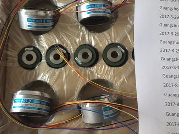
| Brand Name: | Tamagawa |
| Certification: | CE |
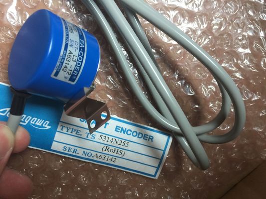
| Model Number: | TS2651N141E78 |
| Minimum Order Quantity: | 1pcs |
|---|---|
| Packaging Details: | carton |
| Delivery Time: | in stock |
| Payment Terms: | T/T, Western Union, MoneyGram |
| Supply Ability: | 100pcs/week |
| TAMAGAWA: | TAMAGAWA | TS2651N141E78: | TS2651N141E78 |
|---|---|---|---|
| Japan: | Japan | Color: | Black |
| Material: | Iron | Temperature: | 30-90 |
| Wire: | Wire | Dimension: | 70mm |
TS2651N141E78
Bit 14 = 1: PNIO - module disconnected
15 -
| Bit 14 = 1: PNIO - module disconnected 15 - |
Bit 18 = 1: Input not available Bit 19 = 1: Output not available |
| 16 to 31 Status information for modules generated by the CPU: Bit 16 = 1: Module disabled |
Bit 20 = 1: Overflow diagnostics buffer Bit 21 = 1: Diagnostics not available Bit 22 - 31: Reserved (always 0) |
| Bit 17 = 1: CiR operation active | Enum The value of the OwnState parameter describes the maintenance |
Guang Zhou Lai Jie Electric Co.,LTD
Please contact with “Tommy” for the price
TS5019N60
TS3653N11E2
TS5313N122
TS2228N33E1
TS4507N1002E200
TS3134N52
OSE5K-6-12-108
TS3667N13E8
TS5013N68
TS3653N12E5
TS5320N632
TS2640N141E172
TS4507N1202E200
OSE5KN-6-12-108
TS3674N37
TS5013N69
TS3653N13E8
TS5420
TS2640N181E100
TS4507N1205E200
TS3166N43
TS3679N2E1
TS5208N131
TS3653N1E1
TS5641N150
TS2640N321E64
TS4507N1229E200
TS3212N32
status of the module.
0 No fault
1 The module or device is disabled.
2 Maintenance required
3 Maintenance demanded
4 Error
5 The module or the device cannot be reached from the CPU (valid for
modules and devices below a CPU).
6 Inputs/outputs are not available.
OwnState Uint16
7 -
Bit array I/O status of the module
0 Bit 0 = 1: No maintenance required
1 Bit 1 = 1: The module or device is disabled.
2 Bit 2 = 1: Maintenance required
3 Bit 3 = 1: Maintenance demanded
IO State Uint16
4 Bit 4 = 1: Error il structure
With the MODE parameter = 2, the diagnostics information details are output in accordance
with the DiagnosticsDetail structure. The following table shows the meaning of the individual
parameter values: With the MODE parameter = 2, the diagnostics information details are output in accordance
with the DNN structure. The following table shows the meaning of the individual parameter
values: SubordinateState UINT Enum Status of the subordinate module (See parameter OwnState of
the DIS structure.)
SubordinateIOState WORD Bitarray Status of the inputs and outputs of the subordinate module (See
parameter IO State of the DIS structure.)
DNNmode WORD Bitarray Bit 0 = 0: Diagnostics enabled
Bit 0 = 1: Diagnostics disabled
Bit 1 to 15: Reserved No error
n The data area in the DETAILS parameter is too small. Not all details of the diagnostic data can be
output.
8080 Value in the MODE parameter is not supported.
8081 Type in the DIAG parameter is not supported with the selected mode (parameter MODE).
8082 Type in the DETAILS parameter is not supported with the selected mode (parameter MODE).
8090 LADDR does not exist.
8091 The selected channel in the CHANNEL parameter does not exist.
80C1 Insufficient resources for parallel executionThe following ladder logic network and DB show how to use the three modes with the three
structures:
● DIS
● DiagnosticsDetail
● DNN In the DB, you must manually type in the data type to access each of the three structures;
there is no dropdown list selection. Type in the data types exactly as shown below:
DNN
DIS
DiagnosticsDetail PWM identifier: Names of enabled pulse generators will become tags in
the "constant" tag table, and will be available for use as the PWM
parameter. (Default value: 0)
ENABLE IN Bool 1=start pulse generator
0 = stop pulse generator
BUSY OUT Bool Function busy (Default value: 0)
STATUS OUT Word Execution condition code (Default value: 0)
The CTRL_PWM instruction stores the parameter information in the DB. The data block
parameters are not separately changed by the user, but are controlled by the CTRL_PWM
instruction.
Specify the enabled pulse generator to use, by using its tag name for the PWM parameter.
When the EN input is TRUE, the PWM_CTRL instruction starts or stops the identified PWM
based on the value at the ENABLE input. Pulse width is specified by the value in the
associated Q word output address.
Because the CPU processes the request when the CTRL_PWM instruction is executed,
parameter BUSY will always report FALSE. If an error is detected, then ENO is set to
FALSE, and parameter STATUS contains a condition code. The pulse width will be set to the initial value configured in device configuration when the
CPU first enters RUN mode. You write values to the Q-word location specified in device