|
| Place of Origin: | Japan |
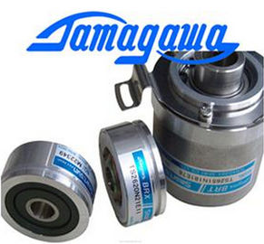
| Brand Name: | Tamagawa |
| Certification: | CE |
| Model Number: | TS2651N1E78 |
| Minimum Order Quantity: | 1pcs |
|---|---|
| Packaging Details: | carton |
| Delivery Time: | in stock |
| Payment Terms: | T/T, Western Union, MoneyGram |
| Supply Ability: | 100pcs/week |
| TAMAGAWA: | TAMAGAWA | TS2651N1E78: | TS2651N1E78 |
|---|---|---|---|
| Material: | Iron | Color: | Black |
| Japan: | Japan | Wire: | Wire |
| Dimension: | 69mm | Temperature: | 20-90 |
TS2651N1E78
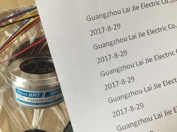
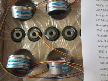
Guang Zhou Lai Jie Electric Co.,LTD
Please contact with “Tommy” for the price
TS3653N1E1
TS5641N150
TS2640N321E64
TS4507N1229E200
TS3212N32
RFH102422
TS3679N3E1
TS5208N111E78
TS3617N47E4
TS1508N211
TS2650N11E78
TS4507N2000E100
TS3214N12
RFH1024-22-1M-68
TS3682N1
TS3617N1E1
TS3624N1E1
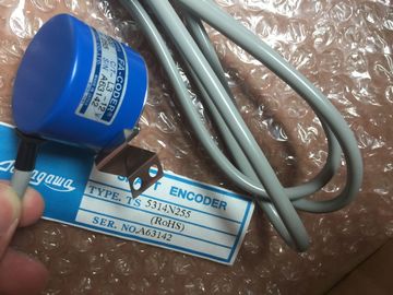
TS1508N255
TS2651N111E78
TS4507N2070E100
TS3214N13
RFH102422IM
TS3682N2
TS3617N1E2
TS3624N21E1
TS1508N257
TS26541N131E78
TS4507N2405E200
TS3214N15
TA8110N2121E802
TS3684N11E3
![]()
![]()
![]()
![]()
| configuration. ● Initial pulse width: Enter your initial pulse width value. The pulse width value can be changed during runtime. |
When you configure the outputs of the CPU or signal board as pulse generators |
| Enter the start address to configure the output addresses. Enter the Q word address where you want to locate the pulse width value |
(for use with the PWM or motion control instructions), the corresponding outputs addresses (Q0.0, Q0.1, Q4.0, and Q4.1) are removed from the Q memory and cannot be used for other |
| NOTICE Pulse-train outputs cannot be used by other instructions in the user program |
If your user program writes a value to an output used as a pulse generator, the CPU does not write that value to the physical output. |
The default location is QW1000 for PWM1, and QW1002 for PWM2. The value at this
location controls the width of the pulse and is initialized to the "Initial pulse width:" value
specified above each time the CPU transitions from STOP to RUN mode. You change this
Q-word value during run time to cause a change in the pulse width.
8.7 Data logging
Your control program can use the Data log instructions to store run-time data values in
persistent log files. The data log files are stored in flash memory (CPU or memory card). Log
file data is stored in standard CSV (Comma Separated Value) format. The data records are
organized as a circular log file of a pre-determined size.
The Data log instructions are used in your program to create, open, write a record, and close
the log files. You decide which program values will be logged by creating a data buffer that
defines a single log record. Your data buffer is used as temporary storage for a new log
record. New current values must be programmatically moved into the buffer during run-time.
When all of the current data values are updated, you can execute the DataLogWrite
instruction to transfer data from the buffer to a data log record.
Use the built-in PLC Web server to manage your data log files. Download recent records, all
records, clear records, or delete log files with the "Data Logs" standard web page. After a
data log file is transferred to your PC, then you can analyze the data with standard
spreadsheet tools like Excel.
8.7.1 Data log record structure
The DATA and HEADER parameters of the DataLogCreate instruction assign the data type
and the column header description of all data elements in a log record.
DATA parameter for the DataLogCreate instruction
The DATA parameter points to memory used as a temporary buffer for a new log record and
must be assigned to an M or DB location.