|
| Place of Origin: | Japan |
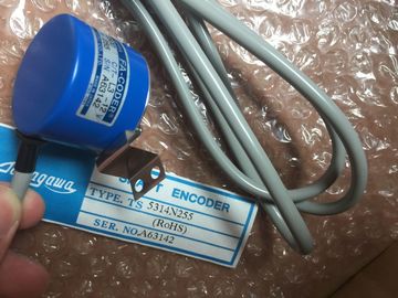
| Brand Name: | Tamagawa |
| Certification: | CE |
| Model Number: | TS5016N60 |
| Minimum Order Quantity: | 1pcs |
|---|---|
| Packaging Details: | carton |
| Delivery Time: | in stock |
| Payment Terms: | T/T, Western Union, MoneyGram |
| Supply Ability: | 1000pcs/week |
| TAMAGAWA: | TAMAGAWA | TS5016N60: | TS5016N60 |
|---|---|---|---|
| Japan: | Japan | Material: | Iron |
| Color: | Black | Temperature: | 20-120 |
| Dimension: | 30mm |
TS5016N60
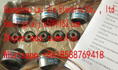
Guang Zhou Lai Jie Electric Co.,LTD
Please contact with “Tommy” for the price
TS3624N3E5
TS3624N3E6
TS3630N1303E9
TS3630N1309E5
TS3630N1306
TS3630N1E1
TS3630N1E2
TS3630N2E3
TS3630N2E4
TS3630N3E5
TS3630N101E2
TS3630N102E4
TS3630N22E3
TS3630N22E4
TS3631N1E1
TS3636N6
TS3641N1E1
TS3641N21E6
TS3641N22E7
TS3641N2E3
TS3641N12E3
TS3641N32
TS3641N38
TS3643N2
TS3643N212E5
TS3643N233E8
TS3653N11E2
TS3653N12E5
TS3653N13E8
![]()
![]()
![]()
![]()
| Response at CPU-STOP Substitute a value/ | value Module |
| Keep last value | Substitute value 0/1 0 Channel |
| Substitute a | See also |
Settings from the digital output module SM 322; DO 16 x DC 24 V/0.5 A
(6ES7322-8BH10-0AB0) (Page 530)
Digital modules
3.24 Digital output module SM 322; DO 16 x DC 24 V/0.5 A: (6ES7322-8BH10-0AB0)
Module data
Manual, 06/2017, A5E00105505-AJ 153
3.24.2 Diagnosis of digital output modules
Introduction
General information in regards to the evaluation of the diagnosis messages can be found in
the chapter Diagnosis of digital modules (Page 59) and the design and content of the
individual bytes in the chapter Diagnosis data from the SM 322; DO 16 x DC24 V/0.5 A
(6ES7322-8BH10-0AB0) (Page 590).
Channel errors are signaled with the channel error display (red LED per channel) and
reported in the data record 1. As soon as at least one channel error display is lit, the group
error display (SF) is also lit.
Module errors are signaled via the diagnostic data record 0/1 and only displayed via the the
group error display (SF).
Group diagnostics
Through the "Group diagnositcs" setting, the message from the channel-specific fields, with
the exception of "external load voltage L+", for "Setting error" and the recognition of a
discrepancy error can be turned off.
Load voltage L+ missing
The approval of the channel diagnositcs "external load point L+" occurs in channel groups
through the diagnostics setting "Missing load voltage L+". This means that if the load voltage
fails, the error will be reported to all four channels of a channel group. Additionally, the
module-specific message occurs in the byte 0 of the diagnostics dataset 0 / 1, "external
auxiliary voltage missing". Even if the diagnostics of "Missing load voltage L+" is turned off
for all channels/channel groups, the recognition within the module remains active. This
means that if there is a failure of at least one load voltage, the module error will always be
reported in the byte 0 of the diagnostics data set 0 / 1 "External auxiliary voltage missing".
Fuse blown
If a fuse is blown, it will always be reported to all four channels of a channel group. In
addition to the channel message, there is always the module-specific message in the byte 3
of the diagnostics dataset 0 / 1 "Fuse defect". Even if the "Group diagnostics" setting is
disabled by all channels, a defective fuse will always be reported as module error in the byte
3 of the diagnostics dataset 0 / 1 "Fuse defect".
Digital modules
3.24 Digital output module SM 322; DO 16 x DC 24 V/0.5 A: (6ES7322-8BH10-0AB0)
Module data
154 Manual, 06/2017, A5E00105505-AJ
Discrepancy error monitoring
For project engineering with the MLFB 6ES7322-8BH10-0AB0, the SM 322 DO 16 x DC24 V
/ 0.5A offers a discrepancy error monitoring.
The approval of the channel discrepancy error monitoring occurs in channel groups through
the "Discrepancy error" diagnostics settings. With an approved discrepancy error monitoring,
the module constantly checks the set and actual status of the corresponding digital outputs.
With a recognized discrepancy, for example, due to a component defect on the digital
module, the corresponding channel group will be turned off and the "Fuse defect" error will
be reported to all affected channels in the channel group. After removal/insertion or restart of
the module, the digital outputs will be reactivated and the discrepancy test runs again.
A discrepancy error is exclusively reported through the "Fuse defect" error. An additional
indication through the byte 3 "Fuse defect" does not occur. Thus, a differentiation between
the actual fuse blown and a discrepancy error is possible.
Description of the Diagnostic Evaluation
You can find a detailed description of how to evaluate diagnostic information in the STEP 7
online help.
3.24.3 Firmware update via HW Config
Introduction
The SM 322; DO 16 x DC 24V/0.5 A can be updated to the newest firmware version
depending on the available compatible functional updates.
The most recent firmware versions are available from your representative or from
the Internet (http://www..com/automation/service&support).
Preconditions / Requirements
● STEP 7 V5.5 +(HSP0217) or higher
● With a central use of the module in a , the firmware update must occur in the
CPU-operating mode STOP. If the CPU is in the operating mode RUN, it may lead tounexpected behavior and the module is only available after a network off/network on.● If the module is used in a distributed IO device ET 200M with active backplane busmodules (removal and insertion allowed), the a firmware update is also possible in theRUN CPU state.
● With a distributed use without active backplane bus modules, the firmware update is alsopossible in the RUN CPU state. Please observe that during the firmware update, thedistributed IO device will be turned off shortly.Digital modules3.24 Digital output module SM 322; DO 16 x DC 24 V/0.5 A: (6ES7322-8BH10-0AB0)Module data
Manual, 06/2017, A5E00105505-AJ 155Firmware update
This is how you update the firmware of a central or distributed module:1. Select the module SM 322; DO 16 x DC 24V/0.5 A in HW-config.
2. Select PLC > Update Firmware.3. Use the "Browse" button to select the path to the firmware files (*.upd).4. Click the "Run" button.– The module performs the firmware update.5. You can find additional information in the STEP 7 Online Help.
Note
? During the firmware update, the OB 83 (alarm due to removing and inserting
modules), the OB 85 (program execution error) and the OB 86 (error due to module
rack failure) are opened. If the diagnostics alarm of the module is approved, the OB 82
(diagnostics alarm) will also be opened during the firmware update. Make sure that the
OB is set correspondingly.
? If the red LED (SF) on the module blinks, an error occurred during the firmware update
and the update must be repeated. In this case, the bootloader version Ex.x.x is
displayed in the online diagnostics.
? A firmware update through HW-config is not permitted if the module is in redundant
mode.Identification of the firmware versionAfter the firmware update, you must label the firmware version on the module.3.24.4 I&M identification dataPropertiesI data: Information about the module, which is normally found on the module casing. I-data is
write-protected. They include:● Hardware release status● Firmware release status● Serial numberM data: System-dependent information (e.g. plant designation).
M data is created during configuration.
Digital modules
3.24 Digital output module SM 322; DO 16 x DC 24 V/0.5 A: (6ES7322-8BH10-0AB0)
Module data156 Manual, 06/2017, A5E00105505-AJAll identification data (I&M) is stored retentively in a module and supports you with thefollowing tasks:● Error search and repair in the system● Testing the system configuration● Finding changes to thesystem hardware.
The SM 322; DO 16 x DC 24V/0.5 A supports:● I&M 0 (identification)● I&M 1 (system identification / location identification)● I&M 2 (installation date)● I&M 3 ( additional information)
Reading and writing the identification data with STEP 7
System-dependent information (M-data) is configured in the properties dialog of the module.
You obtain information on the module (I data) from the module status dialog. The systemdependent
information on the module is displayed here too.
Note
Identification data can only be written for modules if the CPU is in the STOP operating mode.
Reading and writing the identification data with PDMThrough the "Identification" flap, the identification data is evaluated and transferred to themodule. Location identification is not available in PDM.NoteIdentification data can only be written for modules if the CPU is in the STOP operating mode.It is recommended to change at most one entry per download, if applicable, the transferringof the identification data must be activated multiple times.6ES7322-1BH10-0AA0PropertiesProperties of SM 322; DO 16 x DC 24 V/0.5 A High Speed:● 16 outputs, electrically isolated in groups of8● Output current 0.5 A● Rated load voltage 24 V DC● Suitable for solenoid valves, DC contactors and signal lamps● Supports isochronous modele with high-speed counterPlease note when using the module in combination with high-speed counters:
oteWhen using a mechanical contact to switch on the 24-V power supply to SM 322; DO16 x DC 24 V/0.5 A High Speed, its outputs will carry "1" signal for the duration of ca. 50 µs,due to the circuit structure.Channel number② Status display - green
③ Backplane bus interface
Dimensions W x H x D (mm) 40 x 125 x 117
Weight ca. 200 g
Module-specific dataSupports isochronous mode yesNumber of outputs 16Cable length• unshielded• shieldedCurrentconsumption
• from the backplane bus• from load voltage L+ (no-load)
max. 70 mAmax. 110 mAPower loss of the module typ. 5 W
Status, interrupts, diagnosticsStatus display green LED per channel
Interrupts noneDiagnostic functio
Output voltage• "1" signalmin. L + (- 0.8 V)Output current• "1" signalRated valuePermitted range0.5 A
5 mA to 0.6 A
• "0" signal (residual current) Max. 0.5 mA
Output delay (resistive load)
• "0" to "1" transition max. 100 μs
• "1" to "0" transition max. 200 μs