 |
| Place of Origin: | Japan |
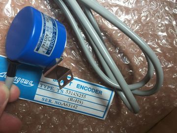
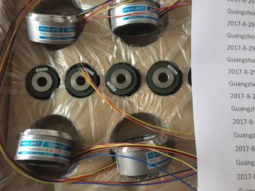
| Brand Name: | Tamagawa |
| Certification: | CE |
| Model Number: | TS2650N11E78 |
| Minimum Order Quantity: | 1pcs |
|---|---|
| Packaging Details: | carton |
| Delivery Time: | in stock |
| Payment Terms: | T/T, Western Union, MoneyGram |
| Supply Ability: | 100pcs/week |
| TAMAGAWA: | TAMAGAWA | Material: | Iron |
|---|---|---|---|
| Color: | Black | Temperature: | 30-120 |
| Dimension: | 40mm | TS2650N11E78: | TS2650N11E78 |
| Wire: | Wire | Japan: | Japan |
TS2650N11E78
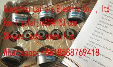
Guang Zhou Lai Jie Electric Co.,LTD
Please contact with “Tommy” for the price
TS3653N3E7
TS3653N3E8
TS3653N3E9
TS3653N13E9
TS3653N44E8
TS3653N4E12
TS3653N14E12
TS3653N58E5
TS3653N65E27
TS3653N81E27
TS3653N78E5
TS3653N94E5
TS3653N181E8
TS3658N3
TS3664N1E1
TS3664N1E2
TS3664N2E3
TS3664N2E4
TS3664N50
TS3664N50
TS3667N1E2
TS3667N11E2
TS3667N2E5
TS3667N2E6
TS3667N3E7
TS3667N3E8
TS3667N13E8
TS3674N37
TS3679N2E1
TS3679N3E1
TS3682N1
TS3682N2
TS3684N11E3
TS3684N12E6
TS3684N13E8
TS3684N1E3
TS3684N2E6
TS3684N3E8
TS3692N103
TS3692N41
TS3692N42
TS3699N112
TS3699N172
TS3699N232
TS3738N1E7
TS3738N1E7
TS3741N3E8
TS374
TS3762N15E4
TS4126N1017E235
TS4127N1017E215
TS4127N1017E235
TS4231N6E17
TS4231N6E17
TS4244N10E24
TS4244N3E24
TS4502N1000E200
TS4502N1202E200
TS4502N2000E100
TS4503N1000E200
TS4503N1007E200
TS4503N1022E100
TS4503N1022E200
TS4503N1202E200
TS4503N1205E200
TS4503N1828E100
TS4503N2000E100
TS4503N2070E100
TS4503N2202E200
TS4503N2036E501
TS4506N1202E200
TS4507N1002E200
TS4507N1202E200
TS4507N1205E200
TS4507N1229E200
TS4507N2000E100
TS4507N2070E100
TS4507N2405E200
TS4507N6205E200
TS4507N8029E200
TS4509N1002E200
TS4509N1202E200
TS4509N1831E200
TS4509N2002E200
TS4509N2405E200
TS4509N7000E100
![]()
![]()
![]()
![]()
| 7.4.3.2 Gray code/binary code converter | |
| When Gray code is set, the Gray code value returned by the absolute value encoder is | |
| converted into binary code. When binary code is set, the values returned by the encoder remain unchanged |
Note
When you set Gray code, the SM 338 always converts the entire encoder value (13, 21, 25
bits). As a result, any leading special bits will influence the encoder value, and the appended
bits may be corrupted.
The transferred encoder value contains the encoder position of the absolute value encoder.
In addition to the encoder position, the encoder transfers additional bits located before and
after the encoder position, depending on the encoder used.
The SM 338 determines the encoder position based on the following settings:
● Scaling, places (0..12), or
● scaling, steps / revolution
Scaling determines the position of the encoder value at the feedback interface.
● "Places" = 1, 2....12 indicates that appended irrelevant bits in the encoder value are
shifted out, and the encoder value is right-aligned in the address area (see the example
below.)
● "Places" = 0 determines that appended bits are retained and available for evaluation.
This may be useful when the absolute value encoder used transfers information in the
appended bits (see manufacturer specifications) which you want to evaluate. Refer also
to chapter "Gray code/binary code converter (Page 502)".
Steps per revolution parameter
Up to 13 bits are available for the steps per revolution parameter. The resultant number of
steps per revolution is displayed automatically according to the "Places" setting.
Example of encoder value scaling
You are using a single-turn encoder with
29 steps = 512 steps per revolution (resolution/360°.)
Your configuration in STEP 7:
● Absolute encoder: 13 bits
● Scaling: 4 places
● Steps per revolution: 512
The freeze function "freezes" the actual encoder values of SM 338. The freeze function is
coupled to the digital inputs DI 0 and DI 1 of SM 338.
The freeze function is triggered by a signal transition (positive edge) a DI 0 or DI 1. Bit 31 = 1
(output address) identifies a frozen encoder value. You can freeze one, two or three encoder
values using one digital input.
Enable the freeze function by setting the corresponding parameters in STEP 7 .
To allows their event-triggered evaluation, the encoder values are retained until the freeze
function is terminated.
Terminating the freeze function
The freeze function must be terminated separately at each encoder input. You acknowledge
the function in the user program by using STEP 7 operation T PAB to set bit 0, 1 or 2 to "xyz"
according to the channel (Program example: refer to chapter "AUTOHOTSPOT").
The acknowledgement resets bit 31 of the corresponding encoder value, and initiates a
refresh of the encoder values. You can freeze the encoder values again after you cleared the
ACK bit at the output address of the module.
In isochronous mode, the acknowledgement is processed at the time To. From this point on,
you can freeze the encoder values again by setting the digital inputs.
Note
The Freeze function is acknowledged automatically when you assign new parameters with
different arguments to the relevant
channel (refer to chapter "AUTOHOTSPOT").
If the parameter are identical the Freeze function remains unaffected
Parametrization SM 338 POS-INPUT
You parameterize the SM 338; POS-INPUT in STEP 7. Always parameterize the module
while the CPU is in STOP mode.
After you completed the parameter assignment, download the parameters from the PG to the
CPU. At its next STOP → RUN transition, the CPU transfers the parameters to the SM 338.
New parameters can not be assigned by the user program.
Parameters of SM 338; POS-INPUT
The table below provides an overview of configurable parameters and defaults for the SM
338.
The defaults apply if you have not set any parameters in STEP 7 (default setting bold)
Enable