 |
| Place of Origin: | Japan |
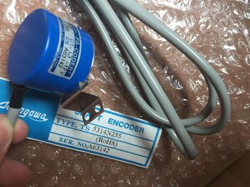
| Brand Name: | Tamagawa |
| Certification: | CE |
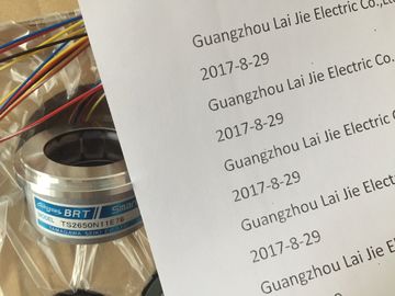
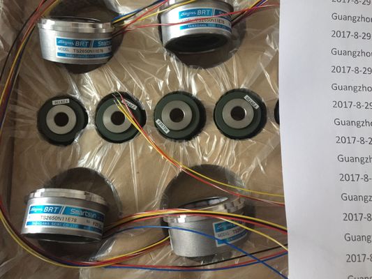
| Model Number: | TS2650N101E78 |
| Minimum Order Quantity: | 1pcs |
|---|---|
| Packaging Details: | carton |
| Delivery Time: | in stock |
| Payment Terms: | T/T, Western Union, MoneyGram |
| Supply Ability: | 100pcs/week |
| TAMAGAWA: | TAMAGAWA | Material: | Iron |
|---|---|---|---|
| Color: | Black | Temperature: | 40-120 |
| Dimension: | 30-120 | Wire: | Wire |
| TS2650N101E78: | TS2650N101E78 |
TS2650N101E78
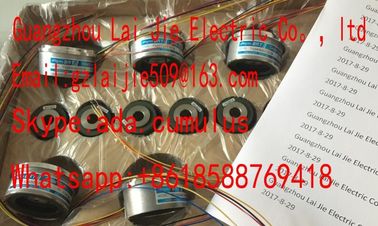
Guang Zhou Lai Jie Electric Co.,LTD
Please contact with “Tommy” for the price
TS4507N1229E200
TS4507N2000E100
TS4507N2070E100
TS4507N2405E200
TS4507N6205E200
TS4507N8029E200
TS4509N1002E200
TS4509N1202E200
TS4509N1831E200
TS4509N2002E200
TS4509N2405E200
TS4509N7000E100
TS4514N1021E200
TS4514N1407E200
TS4514N1828E200
TS4514N2002E200
TS4514N2405E200
TS4515N1202E200
TS4515N2405E200
TS4515N6000E200
TS4602N1000E200
TS4602N6321E100
TS4603N1000E100
TS4603N1000E200
TS4603N1532E200
TS4603N1700E200
TS4603N2002E200
TS4603N7002E200
TS1505N55?
TS1508N211
TS1508N255
TS1508N257
TS1508N260
TS1613N200
TS16N13E12
TS16N18E11
TS2013N191E26
TS2014N181E32
TS2014N311E32
TS2014N312E32
TS2018N303E51
TS20E12
TS20N2E11
TS2142N1E63
TS2151N1E26
TS2151N1E45
TS2151N11E45
TS2640N321E64
TS2641N31E64
TS2650N1E78
TS2650N11E78
TS2650N101E78
TS2651N111E78
TS2651N181E78
TS5000N532
TS5000N632
TS5003N632
TS5005N122
TS5007N122
TS5007N635
TS5208N500
TS5208N510
TS5208N530
TS5208N569
TS5208N576
TS5210N450
TS5210N453
TS5210N458??
TS5210N530
TS5210N54
TS5210N553
TS3684N1E3
TS3684N2E6
TS3684N3E8
TS3684N11E3
TS3684N12E6
TS3684N13E8
TS3617N1E3
TS3617N1E1
TS3617N1E2
TS3617N2E4
TS3617N2E5
TS3617N2E6
![]()
![]()
![]()
| Programmable resolution for each group | Programmable limit value monitoring for 2 channels |
| High-speed update of measured values | Programmable hardware interrupt when limit is exceeded |
| Supports isochronous mode | ● Electrical isolation from the CPU |
Electrically isolated from load voltage (not for 2-wire transducers)
Diagnostics
For information on diagnostics messages at the "group diagnostics" parameter, refer to
chapter Diagnostic messages of analog input modules (Page 296).
Hardware interrupts
Hardware interrupts for channel groups 0 and 1 can be programmed in STEP 7. However,
set a hardware interrupt only for the first channel of a channel group, that is, either at
channel 0, or at channel 2
Measuring principle Actual value conversion
Integration/conversion time/resolution (per channel)
• programmable yes
• Basic conversion time per channel 52 µs
• Resolution (including overshoot range) 14 bits
• Interference frequency suppression at interference frequency
f1 in Hz
none 400 60 50
• Basic execution time of the module (independent of the
number of enabled channels)
Wiring of the signal transmitters
• for voltage measurement
• for current measurement
as 2-wire transducer
as 4-wire transducer
• Load of the 2-wire transducer at L+ = DC 24 V
using a 20-pin front connector
supported
supported
supported
max. 820 Ω
Characteristics linearization none
The analog input module has measuring range modules. The measurement type and range
is configured at the "measuring range" parameter in STEP 7.
The default setting of the module STEP 7 is "voltage" measurement with "± 10V" range. You
can use those default settings without having to program the SM 331;
AI 8 x 14 Bit High Speed in STEP 7.You may have to change the position of the measuring range module to suit the
measurement type and range. See table Setting measuring methods and ranges of analoginput channels. The settings are also printed on the module. Mark the position of themeasuring range module on the front door (see figure).The channels of SM 331; AI 8 x 14 Bit High Speed are arranged in four groups of two
channels. You can assign parameters only to one channel group.SM 331; AI 8 x 14 bits High Speed is equipped with one measuring range module per
channel group.The table below shows the relevant configuration of channel groups. The channel groupnumber is required to program SFC parameters in the user program.Table 6- 14 Assignment of SM 331; AI 8 x 14 bits High Speed channels to channel groups
For information on programming analog modules, refer to the chapter Programming analogmodules