|
| Place of Origin: | Japan |
| Brand Name: | Tamagawa |
| Certification: | CE |
| Model Number: | TS5214N8566 |
| Minimum Order Quantity: | 1pcs |
|---|---|
| Packaging Details: | carton |
| Delivery Time: | in stock |
| Payment Terms: | T/T, Western Union, MoneyGram |
| Supply Ability: | 100pcs/week |
| TAMAGAWA: | TAMAGAWA | TS5214N8566: | TS5214N8566 |
|---|---|---|---|
| COLOR: | BLACK | Temperature: | 40-120 |
| Material: | Iron | Dimension: | 50mm |
| Wire: | Wire |
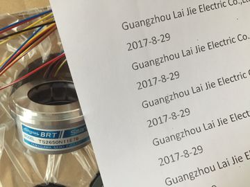
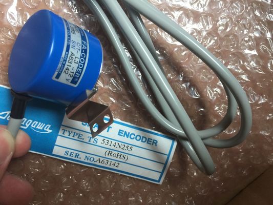
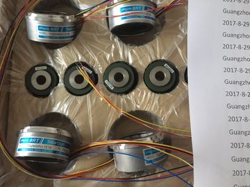
TS5214N8566
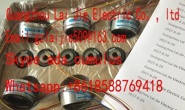
Guang Zhou Lai Jie Electric Co.,LTD
Please contact with “Tommy” for the price
TS3462N1E76
TS2651N1E78
TS2651N131E78
TS2014N181E32
TS3103N40
TS3653N2E5
TS3653N3E8
TS3684N1E3
TS3684N2E6
TS3684N3E8
TS3667N3E8
TS3624N2E3
TS3624N2E4
TS3624N3E6
TS3630N1E1
TS3630N2E3
TS3630N1306
TS3630N1303E9
TS3630N1214E3
TS5013N60
TS5013N61
TS5016N60
TS5013N63
TS5013N64
TS5016N61
TS5013N66
TS5016N63
TS5016N64
TS5017N60
TS5019N60
TS5420N60
TS5778N155
TS5013N68
TS5013N69
TS5208N131
TS5208N23
TS2025N471E69TS2025N471E691E32
TS5208N111E78
TS5208N141E78
TS5631N224
PULSE
GENERATOR
RP-182
750PPR
PULSE
GENERATOR
RP-182
1500PPR
PULSE
GENERATORRP-482E,750PPR
ROTALY
ENCODER
RP-112A-T1,750PPR
ROTALY
ENCODER
RP-112A-T1,1500PPR
ROTALY
ENCODER
RP-112A-T1,3000PPR
ROTALY
ENCODER
RP-132,1500PPR
ROTALY
ENCODER
RP-446Z,750PPR
ROTALY
ENCODER
M-52004
RP872ZL
2048PPR
ROTALY
ENCODER
RP-132A-T1,750PPR
ROTALY
ENCODER
RP-873ZL,2048PPR
ROTALY
ENCODER
RP-886ZN,2500PPR
ROTALY
ENCODER
RP-5354D-CD-4096PPR
ROTALY
ENCODER
RP-132A-T1,600PPR
ROTALY
ENCODER
![]()
![]()
![]()
| Current measurement 4 mA to 20 mA, | |
| 4-wire transducer: wire the used input and unused input of the same channel group in series. |
|
| Line continuity check for the 4 mA to 20 mA measuring range |
If you configured a measuring range of 4 mA to 20 mA, and enabled the line continuity
check, the analog input module logs a wire-break event to diagnostics data when the current
drops below 1.185 mA.
The module also triggers a diagnostics interrupt if this function is enabled in the program.
A wire break can only be signaled by means of the lit SF LED and the diagnostic bytes must
be evaluated in the user program if diagnostics interrupts are disabled.
If you configured a measuring range of 4 mA to 20 mA, disabled the line continuity check,
and enabled diagnostic interrupts, the module triggers a diagnostic interrupt when the
underflow value is reached.
6ES7331-1KF02-0AB0
Properties
● 8 inputs in 8 channel groups
● Programmable resolution for each group (12 bits + sign)
● Measurement type programmable for each channel group:
– Voltage
– Current
– Resistance
– Temperature
● Any measuring range per channel
● Motor protection / temperature monitoring with PTC in accordance with IEC 60034-11-2
type A
● Temperatures recorded via KTY83/110, KTY84/130 silicon temperature sensors
Terminal assignment
The diagrams below show various wiring options. These examples apply to all channels
(channel 0 to 7).
Note
When connecting voltage and current transducers, make sure that the maximum permitted
common-mode voltage CMV of 2 V is not exceeded between the inputs. Prevent measuringerrors by interconnecting the corresponding M- terminals.
Voltage measurement: (± 5V, ± 10V, 1 ... 5V, 0...10V)② Voltage measurement (± 50 mV, ± 500 mV, ± 1 V) (note the input resistance defined in the technicaldata)
③ Equipotential bonding④ Internal supply
⑤ + 5 V from backplane bus
⑥ Logic and backplane bus interface
⑦ Electrical isolation⑧ Multiplexer
⑨ Analog to Digital Converter (ADC)
⑩ Current sourceFigure 6-10 Block diagram and terminal diagram
4-wire transducer (0/4 mA to 20 mA or ± 20 mA)
② 2-wire transducer (4 mA to 20 mA)③ Equipotential bonding④ Internal supply⑤ + 5 V from backplane bus
⑥ Logic and backplane bus interface⑦ Electrical isolation⑧ Multiplexer⑨ Analog to Digital Converter (ADC)⑩ Current sourceFigure 6-11 Block diagram and wiring diagram2-wire connection. Insert a bridge between M and S (no line resistance compensation).② 3-wire connection③ 4-wire connection. The fourthline may not be wired (remains unused)④ 4-wire connection. The fourth line is routed to the terminal strip in the cabinet but is not wired.