 |
| Place of Origin: | Japan |
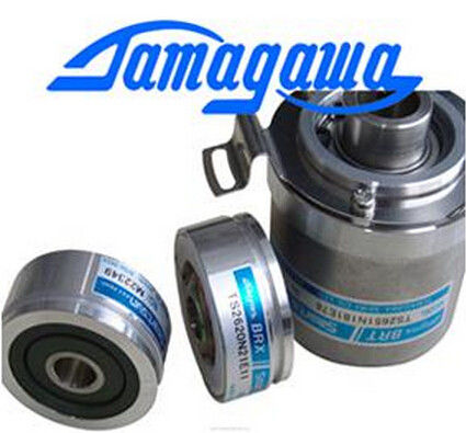
| Brand Name: | Tamagawa |
| Certification: | CE |
| Model Number: | TS2650N11E78 |
| Minimum Order Quantity: | 1pcs |
|---|---|
| Packaging Details: | carton |
| Delivery Time: | in stock |
| Payment Terms: | T/T, Western Union, MoneyGram |
| Supply Ability: | 100pcs/week |
| TAMAGAWA: | TAMAGAWA | TS2650N11E78: | TS2650N11E78 |
|---|---|---|---|
| COLOR: | BLACK | Material: | Iron |
| Temperature: | 40-120 | Japan: | Japan |
| Wire: | Wire |
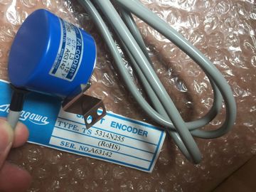
TS2650N11E78
Please contact with “Tommy” for the price
TS4509N1002E200
TS4509N1202E200
TS4509N1831E200
TS4509N2002E200
TS4509N2405E200
TS4509N7000E100
TS4514N1021E200
TS4514N1407E200
TS4514N1828E200
TS4514N2002E200
TS4514N2405E200
TS4515N1202E200
TS4515N2405E200
TS4515N6000E200
TS4602N1000E200
TS4602N6321E100
TS4603N1000E100
TS4603N1000E200
TS4603N1532E200
TS4603N1700E200
TS4603N2002E200
TS4603N7002E200
TS1505N55?
TS1508N211
TS1508N255
TS1508N257
TS1508N260
TS1613N200
TS16N13E12
TS16N18E11
TS2013N191E26
TS2014N181E32
TS2014N311E32
TS2014N312E32
TS2018N303E51
TS20E12
TS20N2E11
TS2142N1E63
TS2151N1E26
TS2151N1E45
TS2151N11E45
TS2640N321E64
TS2641N31E64
TS2650N1E78
TS2650N11E78
TS2650N101E78
TS2651N111E78
TS2651N181E78
TS5000N532
TS5000N632
TS5003N632
TS5005N122
TS5007N122
TS5007N635
TS5208N500
TS5208N510
TS5208N530
TS5208N569
TS5208N576
TS5210N450
TS5210N453
TS5210N458??
TS5210N530
TS5210N54
TS5210N553
TS3684N1E3
TS3684N2E6
TS3684N3E8
TS3684N11E3
TS3684N12E6
TS3684N13E8
TS3617N1E3
TS3617N1E1
TS3617N1E2
TS3617N2E4
TS3617N2E5
TS3617N2E6
TS3617N2E7
![]()
![]()
![]()
| Maximum voltage at voltage input U+ (destruction limit) max. | |
| 30 V, continuous Maximum voltage at voltage inputs M+, |
|
| M-, S- (destruction limit) max. 12 V continuous; 30 V for a duration of max. 1 s |
Maximum current at current input I+ (destruction limit) 40 mA
Wiring of the signal transmitters using a 40pin front connector
• for voltage measurement
• for current measurement
– as 2-wire transducer
– as 4-wire transducer
supported
supported, with external supply
supported
• for resistance measurement
with 2-wire connection
with 3-wire connection
with 4-wire connection
supported
supported
supported
Characteristics linearization programmable
• for resistance thermometers Pt 100 Standard / Klima
Ni 100 Standard / Klima
Ni 1000 Standard / Klima
LG-Ni 1000 Standard / Klima
• Technical unit of temperature measurement Degrees Centigrade, degrees Fahrenheit, Kelvin
Thermal resistance
RTD-4L (linear, 4-wire connection)
(temperature measurement)
Silicon temperature sensors
Pt 100 Klima / Standard
Ni 100 Klima / Standard
Ni 1000 Klima / Standard
LG-Ni 1000 Klima / Standard
KTY83/110
KTY84/130
You will find a description of the general procedure for assigning parameters to analog
modules in section Programming analog modules (Page 294)
Measurement
• Measurement type disabled
Voltage V
Current I
Resistance R, PTC
Thermal resistance RTD,
silicon temperature sensors
V
dynamic Channel
• Measuring range Voltage
± 50 mV; ± 500 mV; ±1 V;
1 V to 5 V
± 5 V; 0 V to 10 V; ± 10 V
± 10 V
Current
0 mA to 20 mA; 4 mA to 20 mA; ± 20 mA
± 20 mA
Resistance
0 Ω to 600 Ω; 0 kΩ to 6 kΩ; PTC
600 Ω
Thermoelectric resistance (linear)
Pt 100 Klima / Standard
Ni 100 Klima / Standard
Ni 1000 Klima / Standard
LG-Ni 1000 Klima / Standard
KTY83/110
KTY84/130
Pt 100
Standard
• Temperature coefficient Pt 100
0.003850 Ω/Ω/ °C (IST-90)
Ni 100 / Ni 1000
0.006180 Ω/Ω/ °C
LG-Ni 1000
0.005000 Ω/Ω/ °C
0,003850
• Interference frequency
suppression
50 Hz; 60 Hz 50 Hz
Module
• Temperature unit Degrees Centigrade, degrees Fahrenheit,
Kelvin*
degrees
Centigrade
* only Pt 100 Standard, Ni 100 Standard, Ni 1000 Standard, LG-Ni 1000 Standard
The spare parts of the SM 331-1KF02 are compatible with the SM 331-1KF01 and are
configured with HSP 2067. HSP 2067 can be installed for STEP7 V5.4, SP5 and higher and
is included for STEP7 V5.4, SP6 and higher.
Unused channels
Set the "disabled" value at the "measurement type" parameter for unused channels. This
setting reduces module cycle times.
Interconnect the M- terminals of unused channels.
Using PTC resistors
PTCs are suitable for monitoring the temperature of or providing thermal protection for
complex drives and transformer windings. The module has no analog values when PTC
resistances are used. Status information on fixed temperature ranges are displyed instead of
analog values.
● When setting the parameters, select measurement type R "Resistance" and measuring
range "PTC".
● Connect the PTC (see "Terminal diagram for resistance measurement").
● Use PTC resistors that comply with IEC 60034-11-2 (previously, PTC thermistors that
complied with DIN/VDE 0660, Part 302).
● Sensor data for the PTC resistor:
Only bits 0 and 2 in the process image input are relevant for evaluation. You can use bits
0 and 2 to monitor the temperature of a motor, for example.
Bits 0 and 2 in the process image input cannot be saved. When assigning parameters,
make sure that the motor, for example, starts up in a controlled manner (by means of an
acknowledgment).
Bits 0 and 2 can never be set at the same time; they are set one after the other.
Using silicon temperature sensors
Silicon temperature sensors are commonly used to detect temperatures in motors.
● When assigning the parameters, select measurement type "thermoresistor" and
measuring range "KTY83/110" or "KTY84/130".