 |
| Place of Origin: | Japan |
| Brand Name: | Tamagawa |
| Certification: | CE |
| Model Number: | TS2014N312E32 |
| Minimum Order Quantity: | 1pcs |
|---|---|
| Packaging Details: | carton |
| Delivery Time: | in stock |
| Payment Terms: | T/T, Western Union, MoneyGram |
| Supply Ability: | 1000pcs/week |
| Tamagawa: | Tamagawa | TS2014N312E32: | TS2014N312E32 |
|---|---|---|---|
| Material: | Iron | Color: | Black |
| Temperature: | 20-120 | Dimension: | 50mm |
| Wire: | Wire |
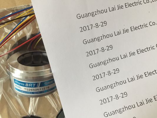
TS2014N312E32
Guang Zhou Lai Jie Electric Co.,LTD
Please contact with “Tommy” for the price
TS3617N1E3
TS2014N185E32
TS4602N1000E200
TS4603N1000E200
TS3617N2E6
TS5214N566
TS5205N450
TS5213N551
TS5208N122
TS5208N23
TS5778N171
TS5210N53
TS5320N510
TS5000N632
TS5212N510
TS5213N510
TS5312N616
TS208N101
TS5208N130
TS5213N530
TS5013N68
TS5214N566
TS5200N500
TS5305N616
TS5669N220
TS5214N564
TS5246N158
TS5667N650
TS5213N551
TS5668N20
TS5667N120
TS5667N420
TS5246N160
TS5312N512
TS5208N122
TS5641N151
TS5270N15
TS5308N616
TS5213N510
TS2014N181E32
TS5308N616
TS3462N1E76
TS5214N561
TS5214N510
TS2014N182E32
TS3653N2E5
TS5320N510
TS5016N-60
TS5016N60
TS2651N111E78
TS2014N181E32
TS2651N131E78
TS2651N141E78
TS5214N566
TS5205N450
TS5308N616
TS3462N1E76
48-2500P8-L6-5V
TS5214N561
TS5214N510
TS2014N182E32
TS3653N2E5
TS5320N510
TS5016N-60
TS5016N60
TS2651N111E78
TS2014N181E32
TS5013N60,
TS5013N61,
TS5016N60,
TS5017N60,
TS5013N68,
TS5
013N69
![]()
![]()
![]()
![]()
| • horizontal mounting position | to 40 °C max. 2 A Electrical isolation • between channels and the backplane bus |
| to 40 °Cto 60 °Cmax. 4 A | between channels in groups of |
| max. 2 A • vertical mounting position |
Maximum potential difference |
between Minternal and outputs 230 VAC
• between outputs of different groups 500 VAC
Isolation test voltage 1500 VAC
Current consumption
• from the backplane bus
• from load voltage L1 (no-load)
max. 100 mA
max. 2 mA
Power loss of the module typ. 8.6 W
Status, interrupts, diagnosticsStatus display green LED per channelInterrupts noneDiagnostic functions• Group error displayyesred LED (SF) 2)
Properties of digital output module SM 322; DO 8 x AC 120/230 V/2 A ISOL:
● 8 outputs, electrically isolated
● Group error display
● Channelspecific status LEDs
● Configurable diagnostics● Programmable diagnostic interrupt● Programmable substitute value output● Output current 2 A● Rated load voltage 120/230 V AC● Suitable for AC solenoid valves, contactors, motor starters, FHP motors and signal lamps● Supports parameter reassignment in RUNGroup error display - red
② Backplane bus interface③ Channel number
④ Status display - greenDimensions W x H x D 40 x 125 x 117
Weight approx. 275 gModule-specific data
Supports parameter reassignment in RUN Yes• Reaction of non-programmed outputs Return the output value which was valid before theparameterization
Supports isochronous mode NoNumber of outputs 8Cable length
• unshielded• shielded
max. 600 mmax. 1000 m
Voltages, currents, electrical potentials
Rated load voltage L1 120/230 V ACTotal current of outputs (module)• Horizontal mounting position
to 40 °Cto 60 °Cmax. 8 Amax. 4 A
• vertical mounting position
to 40 °C
max. 4 A
Electrical isolation
• between channels and the backplane bus yes
• between channels
in groups of
yes
1
Maximum potential difference
• between Minternal and outputs 230 V AC
• between outputs 500 V AC
Isolation test voltage
• between Minternal and outputs 1500 V AC
• between outputs of different groups 2000 V AC
Current consumption
• from the backplane bus
• from load voltage L1 (no-load)
max. 100 mA
max. 2 mA
Power loss of the module typ. 8.6 W
Status display green LED per channel
Interrupts
• Diagnostic interrupt programmable
Diagnostic functions
• Group error display red LED (SF)
Actuator selection data
Output voltage
• "1" signal
– At maximum current
– At minimum current
min. L1 (-1.5 V)
min L1 (-8.5 V)
Output current
• "1" signal
Rated value
permissible range at 0 °C to 40 °C
permissible range at 40 °C to 60 °C
Maximum inrush current (per group)
2 A
10 mA to 2 A
10 mA to 1 A
20 A (with two half-waves)
• "0" signal (residual current) max. 2 mA
Zero transition max. 60 V
Size of the motor starter max. size 5 to NEMA
Lamp load max. 50 W
Wiring two outputs in parallel
• for redundant load control supported
• for performance increase not supported
Control of a digital input supported
Switching frequency
• with resistive load max. 10 Hz
• with inductive load to IEC 947-5-1, AC 15 max. 0.5 Hz
• with lamp load max. 1 Hz
Short circuit-proof output yes, 3.15 A / 250 V fuse, fast-blow
Wiring of the actuators Using a 40-pin front connector
Note
The outputs must be protected by a high-speed, fast-blow 3.15 A 250 V AC fuse. Hazardous
areas to National Electric Code must be determined safe before you remove/replace the
fuse. Removal and replacement may only be possible using a suitable tool.
Special considerations must be given if you use the Configuration in RUN function.SF LED is lit:Status before re-configuration diagnostics on, SF LEDs lit among others (on CPU, IM ormodule), although diagnostics are no longer pending and the module is operating correctly.Solution: Only change the configuration when no diagnostics are pending for the module or
Pulling and plugging the module.The table below lists the configurable parameters of SM 322; DO 8 x AC120/230 V/2 A
ISOL, including defaults.The defaults apply if you have not set any parameters in STEP 7.Table 3- 32 Parameters of SM 322; DO 8 x AC 120/230 V/2 A ISOLEnable• Diagnostic interrupts yes/no no dynamicModuleReaction to CPU STOP Set substitute value (SSV)