 |
| Place of Origin: | Japan |
| Brand Name: | Tamagawa |
| Certification: | CE |
| Model Number: | TS2151N11E45 |
| Minimum Order Quantity: | 1pcs |
|---|---|
| Packaging Details: | carton |
| Delivery Time: | in stock |
| Payment Terms: | T/T, Western Union, MoneyGram |
| Supply Ability: | 100pcs/week |
| TAMAGAWA: | TAMAGAWA | TS2151N11E45: | TS2151N11E45 |
|---|---|---|---|
| Japan: | Japan | Material: | Iron |
| Color: | Black | Temperature: | 30-120 |
| Wire: | Wire |
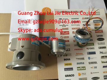
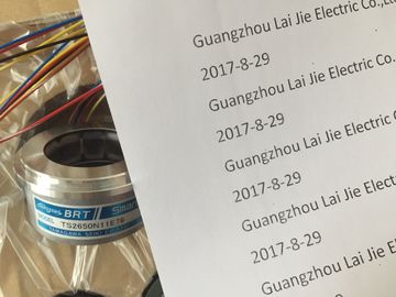
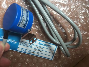
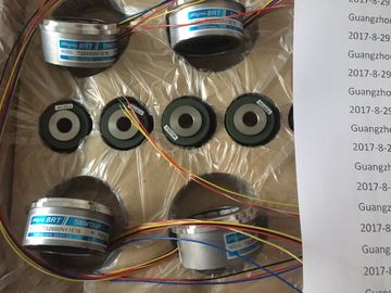
TS2151N11E45
Guang Zhou Lai Jie Electric Co.,LTD
Please contact with “Tommy” for the price
TS3624N21E2
TS3624N1E2
TS3624N102E4
TS3624N103E5
TS3624N203E5
TS3624N22E4
TS3624N23E5
TS3624N2E3
TS3624N2E4
TS3624N3E5
TS3624N3E6
TS3630N1303E9
TS3630N1309E5
TS3630N1306
TS3630N1E1
TS3630N1E2
TS3630N2E3
TS3630N2E4
TS3630N3E5
TS3630N101E2
TS3630N102E4
TS3630N22E3
TS3630N22E4
TS3631N1E1
TS3636N6
TS3641N1E1
TS3641N21E6
TS3641N22E7
TS3641N2E3
TS3641N12E3
TS3641N32
TS3641N38
TS3643N2
TS3643N212E5
TS3643N233E8
TS3653N11E2
TS3653N12E5
TS3653N13E8
![]()
![]()
![]()
![]()
| Pulling and plugging the module. | |
| 3.12.1 Parameters of SM 321; DI 16 x DC 24/125 V | |
| rogramming The general procedure of programming digital modules is described in the chapter |
Programming digital modules.
Parameters of SM 321; DI 16 x DC 24 V/125 V
The table below shows an overview of configurable parameters and their default settings for
SM 321; DI 16 x DC 24 V/125V.
The default settings apply if you have not set any parameters in STEP 7.
Table 3- 17 Parameters of SM 321; DI 16 x DC 24 V/125 V
Parameters Range of values Default Parameter
typeEfficiency rangeEnable• Diagnostic interrupt• Hardware interruptYes/NoYes/NoNoNodynamic ModuleInput delay/voltage type 0.1 ms (DC)0.5 ms (DC)3 ms (DC)15 ms (DC)20 ms (DC/AC)
3 ms (DC) static ModuleDiagnostics• Wire break Yes/No No static ChannelHardware interrupt trigger•Positive edge• Negative edgedynamic Channel3.12 Digital input module SM 321; DI 16 x DC 24/125 V; with hardware and diagnostic interrupts(6ES7321-7EH00-0AB0)
Module dataManual, 06/2017, A5E00105505-AJ 99Tolerances of the programmable input delaysTable 3- 18 Tolerances of the input delays of SM 321; DI 16 x DC 24 V/125 VProgrammed input delayTolerance0.1 ms 80 μs to 200 μs0.5 ms 580 μs to 700 μs3 ms (default) 3.1 ms to 3.7 ms15 ms 15.1 ms to 18.1 ms20 ms20.1 ms to 24.1 msNoteThe timers for the input delay are only valid for reading in the status. In thecase of wirebreak,"Wire-break diagnostics" is only triggered approx. 40 ms after the reading in ofthevalue.3.12.2 Diagnostics of SM 321; DI 16 x DC 24/125 VDiagnostic messages of SM 321; DI 16 xDC24 V/125 VThe table below shows an overview of the diagnostic messages of SM321; DI 16 x DC 24 V/125 V.Table 3- 19 Diagnostic messages of SM 321; DI 16 x DC 24 V/125 VDiagnostic message LEDScope of diagnostics programmableWire break SF ChanneNo channel parameters SF ChannelYesNo/incorrect parameters in module SF ModuleNoTime monitoring activated (watchdog) SFModuleEPROM fault SF ModuleRAM fault SF ModuleHardware interrupt lost SF ModuleNote
To detect the errors indicated by programmable diagnostic messages, you must have
programmed the digital module accordingly in STEP 7.
Digital modules
3.12 Digital input module SM 321; DI 16 x DC 24/125 V; with hardware and diagnostic interrupts (6ES7321-
7EH00-0AB0)Module data100 Manual, 06/2017, A5E00105505-AJSpecial features of diagnosticsThe SM 321; DI 16 x DC 24 V/125 V supplies 9-byte diagnostic data (diagnostic data set 0with a length of 4 bytes and the diagnostic data set 1 with a length of 9 bytes).The wire-break diagnostics is only reported in the channel error vector of the data set 1(bytes 7 and 8). Each channel that reports an error in the channel errror vector has a wirebreak.You can find additional information, in chapter Structure and content of diagnosticsdata, byte 0 and up (Page 584).Causes of error and troubleshootingTable 3- 20 Diagnostics messages of SM 321; DI 16 x DC 24 V/125V, causes of error and troubleshootingDiagnostic message Possible cause of error To correct or avoid errorIncorrect module parameters
mplausible parameter or combination thereof Program the moduleTime monitoring activated(watchdog)
Infrequent high electromagnetic interference Eliminate the interference
Module defective Replace the module
EPROM fault Infrequent high electromagnetic interference Eliminate interference and cycle the powersupply of CPU off/on.Module defective Replace the moduleRAM fault Infrequent high electromagnetic interference Eliminate interference and cycle the powersupply of CPU off/on.Module defective Replace the moduleHardware interrupt lost The module can not output an interrupt, becausethe previous interrupt was notacknowledged; possibly a configuration errorChange interrupt processing in the CPU, andreprogram the module as requiredThe error persists until the module is assigned
new parametersModule not programmed Startup error Program the module3.12.3 Interrupts of SM 321; DI 16 x DC 24/125 VIntroductionThis chapter describes the interrupt reaction of SM 321; DI 16 x DC 24 V/125V. Always
distinguish between the following interrupts:● Diagnostic interrupt● Hardware interruptFor detailed information on the OBs and SFCs mentioned below, refer to the STEP 7 OnlineHelp.Digital modules3.12 Digital input module SM 321; DI 16 x DC 24/125 V; with hardware and diagnostic interrupts (6ES7321-7EH00-0AB0)
Module data
Manual, 06/2017, A5E00105505-AJ 101
Enabling interrupts
There is no default interrupt setting, i.e. interrupts are disabled if parameters are not set
accordingly. You can enable interrupts in STEP 7 (see the chapter Parameters of
SM 321; DI 16 x DC 24 V ).
Diagnostic interrupt
When diagnostic interrupts are enabled, incoming error events (initial occurrence) and
outgoing error events (error is cleared) are reported by means of an interrupt.
The CPU interrupts user program execution in order to process diagnostic interrupt OB82.
You can call SFC51 or 59 in OB82 in the user program to view detailed diagnostics data
output by the module.
Diagnostics data remain consistent until the program exits OB82. The module acknowledges
the diagnostic interrupt when the program exits OB82.
Hardware interrupt
SM 321; DI 16 x DC 24 V/125V can trigger a hardware interrupt for each channel group at
the positive, negative, or both edges of a signal transition.
You perform parameter assignment for each channel separately. The parameters can be
changed at any time (in RUN mode in the user program.)
Active hardware interrupts trigger hardware interrupt processing in the CPU (OB40) and
interrupt execution of the user program or of object classes with lower priority in the CPU.
You can define the response of the AS to signal edge transitions in the user program of
hardware interrupt OB40. The module acknowledges the hardware interrupt when the
program exits the hardware interrupt OB.
The module can save one interrupt per channel to the stack. If no higher priority classes are
pending processing, the CPU processes the buffered interrupts (of all modules) in the order
of their occurrence.
Hardware interrupt lost
A "Hardware interrupt lost" diagnostic interrupt is generated if a successive interrupt istriggered at the channel previously saved to the stack and which has not yet been processedby the CPU.The CPU does not register any further interrupts at this channel unless it has completedprocessing of the queued interrupts of the same channel.Digital modules
3.12 Digital input module SM 321; DI 16 x DC 24/125 V; with hardware and diagnostic interrupts (6ES73217EH00-0AB0)The relevant hardware interrupt-triggering channel is logged in the OB40_POINT_ADDRvariable of the start information of OB40. The figure shows the bit assignments of DWORD 8
in the local data.Byte Variable Data type Descripti6/7 OB40_MDL_ADDR WORD B#16#0 Address of the interrupt-triggering module
tarting
t 8OB40_POINT_ADDR DWORD see the figure
belowIndication of the interrupt-triggering inputFigure 3-8 Start Information of OB40: which event has triggered the hardware interruptDigital modules3.13 Digital input module SM 321; DI 16 x DC 24 V; source input; (6ES7321-1BH50-0AA0)
Module dataManual, 06/2017, A5E00105505-AJ 1033.13 Digital input module SM 321; DI 16 x DC 24 V;source input;(6ES7321-1BH50-0AA0)Order number6ES7321-1BH50-0AA0PropertiesProperties of SM 321; DI 16 x DC 24 V; source input:● 16 inputs, source input, electrically isolated in groups of 16● Rated input voltage 24 V DC