 |
| Place of Origin: | Japan |
| Brand Name: | Tamagawa |
| Certification: | CE |
| Model Number: | TS2641N31E64 |
| Minimum Order Quantity: | 1pcs |
|---|---|
| Packaging Details: | carton |
| Delivery Time: | in stock |
| Payment Terms: | T/T, Western Union, MoneyGram |
| Supply Ability: | 100pcs/week |
| Tamagawa: | Tamagawa | TS2641N31E64: | TS2641N31E64 |
|---|---|---|---|
| Japan: | Japan | COLOR: | BLACK |
| Material: | Iron | Temperature: | 30-120 |
| Wire: | Wire | Dimension: | 30mm |
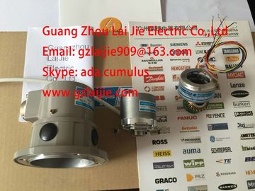
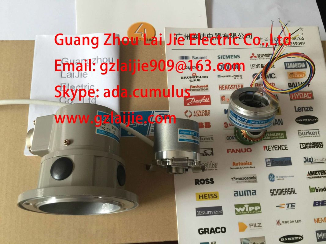
TS2641N31E64
Guang Zhou Lai Jie Electric Co.,LTD
Please contact with “Tommy” for the price
TS3667N1E2
TS3667N11E2
TS3667N2E5
TS3667N2E6
TS3667N3E7
TS3667N3E8
TS3667N13E8
TS3674N37
TS3679N2E1
TS3679N3E1
TS3682N1
TS3682N2
TS3684N11E3
TS3684N12E6
TS3684N13E8
TS3684N1E3
TS3684N2E6
TS3684N3E8
TS3692N103
TS3692N41
TS3692N42
TS3699N112
TS3699N172
TS3699N232
TS3738N1E7
TS3738N1E7
TS3741N3E8
TS374
TS3762N15E4
TS4126N1017E235
TS4127N1017E215
TS4127N1017E235
TS4231N6E17
TS4231N6E17
TS4244N10E24
TS4244N3E24
TS4502N1000E200
TS4502N1202E200
TS4502N2000E100
TS4503N1000E200
![]()
![]()
![]()
![]()
| Supports parameter reassignment in RUN | |
| Channel-based configurable diagnostics | |
| Programmable diagnostic interrupt |
Channel-based configurable hardware interrupts
● Programmable input delays
WARNING
• Electrical hazard arises with electric circuits operated with voltages
– >30 Veff and 42.4 Vpeak
– 60 VDC.
• It is not permitted to mix electrically safe and dangerous contact input voltages on the 16
inputs of the same module.
Digital modules
3.12 Digital input module SM 321; DI 16 x DC 24/125 V; with hardware and diagnostic interrupts (6ES7321-7EH00-0AB0)
Module data
Manual, 06/2017, A5E00105505-AJ 95
Wiring and block diagram of SM 321; DI 16 x DC 24 V/125 V
① Channel number
② Status displays - green
Error displays - red
③ Backplane bus interface
Wiring diagram of the shunt circuit of the sensors
For wire-break detection, it is necessary to connect a shunt resistor to the transducer
contacts.
Figure 3-7 Wiring diagram of the shunt circuit of transducers of SM 321; DI 16 x DC 24 V/125 V
Digital modules
3.12 Digital input module SM 321; DI 16 x DC 24/125 V; with hardware and diagnostic interrupts (6ES7321-
7EH00-0AB0)Module data96 Manual, 06/2017, A5E00105505-AJThe resistance used depends on the module's rated inputvoltageTable 3- 16 Dependence on ratedinputvoltage and resistanceRated input voltage L+ Resistance Rs24 VDC 43 kΩ48 V DC 100 kΩ125 V DC 300 kΩSM 321; DI 16 x DC 24 V/125V - Technical specificationsTechnical specifications
Dimensions and weighDimensions W x H x D (mm) 40 x 125 x 117Weight approx. 200 g
Module-specific dataSupports isochronous mode NSupports parameter reassignment in RUN Yes
Response of non-programmed inputs return the process value which was valid beforeconfigurationAccuracy of the time stamp > 5 ms*Number of inputs 16Cable length• unshielded• shieldedmax. 600mmax. 1000 mVoltages, currents, electrical potentialsNumber of simultaneously controlled inputs• Horizontal mounting position to 60 °C– L+ = 146 VDC– L+ = 125 VDC– L+ = 100 VDC1216• Vertical mounting position to 40 °C– L+ = 146 VD–L+ = 125 VDC– L+ = 100 VDC8116Electrical isolatio•between channels and thbackplanebus• between channelsYesNMaximum potential difference• between different circuits 300 V DC / 250 V ACIsolation test voltage 3500 VDC3.12 Digital input module SM 321; DI 16 x DC 24/125 V; with hardware anddiagnostic interrupts(6ES7321-7EH00-0AB0)Module dataManual, 06/2017, A5E00105505-AJ 97Technical specificationsCurrent consumption• from the backplane bus max. 90 mAPower loss of the module• L+ = 24 V• L+ = 100 V
typ. 2 Wtyp. 6.5 WStatus, interrupts, diagnosticsStatus displays green LED per channelInterrupts• Hardware interrup• Diagnostic interrupt
Wire breakprogrammableprogrammableprogrammableDiagnostic functions programmable
• Group error display red LED (SF)• Reading diagnostics information supported
Monitoring for
• Wire break yes, sensing I < 1 mAEncoder selection dataInput voltage
• Rated value• "1" signal
• "0" signalFrom 15 to 146 V
from -146 V to + 5 VInput current• "1" signal Typ. 3.5 mAInput characteristics to IEC 61131, Type 1Connection of 2-wire BEROs
Permissible quiescent currentsupported
max. 1 mAWiring of the signal transmitters with 40-pin front connectorTime/frequency
Input delay• programmable• Rated valueYestyp. 0.1/0.5/3/15/20 ms**Fixed current limitation of the sensorfor wire-break detection See previous table for dependence on ratedinputvoltage and resistanceOvervoltage protection Dehnconnect RK DCO RK ME110; Art. No. 919 923 To obtain a time stamp accuracy of < 1 ms, the input delay must be configured to 0.1 ms.** To obtain a high immunity tointerference, use a shielded cable and set input delay to 0.1 ms.Digital modules3.12 Digital inputmodule SM 321; DI 16 x DC 24/125 V; with hardware and diagnostic interrupts (6ES7321-7EH00-0AB0)Module data98 Manual, 06/2017, A5E00105505-AJConfiguration in RUNSpecial considerations must be given ifyou use the Configuration in RUN function.SF LED is lit:Status before re-configuration diagnostics on, SFLEDs lit among others (on CPU, IM ormodule), although diagnostics are no longer pending and the module is operating correctly.Solution:● Only change the configuration when no diagnostics are pending for the module or