 |
| Place of Origin: | Japan |
| Brand Name: | Tamagawa |
| Certification: | CE |
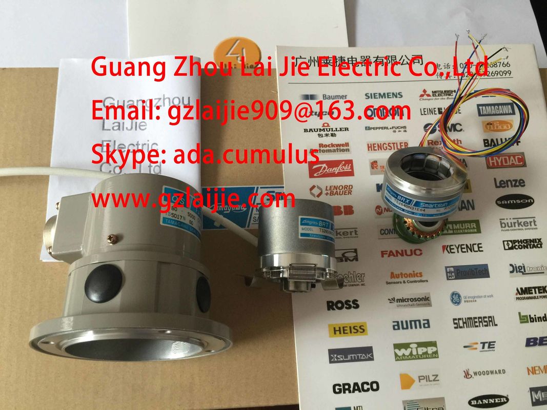
| Model Number: | TS2650N1E78 |
| Minimum Order Quantity: | 1pcs |
|---|---|
| Packaging Details: | carton |
| Delivery Time: | in stock |
| Payment Terms: | T/T, Western Union, MoneyGram |
| Supply Ability: | 100pcs/week |
| TAMAGAWA: | TAMAGAWA | TS2650N1E78: | TS2650N1E78 |
|---|---|---|---|
| Japan: | Japan | Material: | Iron |
| Color: | Black | Temperature: | 40-120 |
| Dimension: | 40mm |
TS2650N1E78
Guang Zhou Lai Jie Electric Co.,LTD
Please contact with “Tommy” for the price
TS4244N10E24
TS4244N3E24
TS4502N1000E200
TS4502N1202E200
TS4502N2000E100
TS4503N1000E200
TS4503N1007E200
TS4503N1022E100
TS4503N1022E200
TS4503N1202E200
TS4503N1205E200
TS4503N1828E100
TS4503N2000E100
TS4503N2070E100
TS4503N2202E200
TS4503N2036E501
TS4506N1202E200
TS4507N1002E200
TS4507N1202E200
TS4507N1205E200
TS4507N1229E200
TS4507N2000E100
TS4507N2070E100
TS4507N2405E200
TS4507N6205E200
TS4507N8029E200
TS4509N1002E200
TS4509N1202E200
TS4509N1831E200
TS4509N2002E200
TS4509N2405E200
TS4509N7000E100
TS4514N1021E200
TS4514N1407E200
TS4514N1828E200
TS4514N2002E200
TS4514N2405E200
![]()
![]()
![]()
![]()
| etween the actual reference temperature and calibrating temperature. | Terminate the compensating box at the COMP terminals of the module; |
| This difference induces a positive or negative compensating voltage, |
the compensating box must be installed at the reference junction of the thermocouples. |
| which is added to the thermoelectrical voltage |
The compensating box |
be supplied with an electrically isolated voltage. The power supply module must provide
adequate noise filtering, for example, by means of grounded cable shielding.
The terminals for the connection of the thermocouple on the compensating box are not
required and must therefore be jumpered (for example, see figure Connection of
thermocouples to reference junction)
Restrictions:
● The channel group parameters always apply to the all its channels (for example, input
voltage, integrating time etc.)
External compensation with connection of the compensating box to the COMP
connections of the module can only be made for one thermocouple type. That is, all
channels that work with external compensation must use the same type.
If all thermocouples connected to the module's inputs share a common reference junction,
compensate the circuit as follows:
Use a compensating box with a reference junction. You must order compensating box from
external companies. Contact your Siemens representative or Industry Online Support on the
Internet
If all thermocouples connected to the module's inputs share a common reference junction,
compensate the circuit as follows:
The analog output modules can be used as current or voltage source for loads and
actuators.
Cables for analog signals
Always use shielded twisted-pair cables to wire analog signals. Form two twisted pairs of the
QV and S+, and M and S- signals in order to reduce interference. Connect both ends of the
analog cable shield to ground.
Any potential difference between the cable ends may cause an equipotential current on the
shield and disturbance on analog signals. Avoid this situation by grounding only one end of
the shielding.
Electrically isolated analog output modules do not have a galvanic interconnection between
the reference point of measuring circuit MANA and the CPU's M terminal.
Always use electrically isolated analog input modules if there is any risk of potential
difference Viso developing between the reference point of measuring circuit MANA and the M
terminal of the CPU. Use an equipotential bonding conductor to interconnect the MANA
terminal and the M terminal of the CPU, in order to prevent Viso from exceeding the permitted
value.
Non-isolated analog output modules
When using on-isolated analog output modules, always interconnect the reference point
MANA of the of measuring circuit with terminal M of the CPU. Wire the MANA terminal to the M
terminal of the CPU. Any potential difference between MANA and the M terminal of the CPU
could otherwise corrupt the analog signal.
The voltage outptus support the wiring and connecting of 2-wire and 4-wire loads. Certain
analog output modules, however, do not support both types of wiring and connecting.
Wiring 4-wire loads to the voltage output of an electrically isolated module
The 4-wire load circuit returns high precision. Wiring and connecting the S- and S+ sense
lines directly to the load. This allows direct measurement and correction of the load voltage.
Interference or voltage dips may lead to potential differences between the sense line S- and
the reference loop of analog circuit MANA. This potential difference may not exceed set limits.
Any potential difference above limits has a negative impact on analog signal precision.
Wire the loads to the QV terminals and to the reference point of measuring circuit MANA.
Interconnect terminal S+ to QV with terminal S to MANA in the front connector.
A 2-wire circuit does not provide for compensation of line impedance.
Wire and connect the loads to QI and to the reference point of analog circuit MANA of a
current output.
Wiring and connecting loads to a current output of an electrically isolated analog output
module
On analog modules with a resolution of < 16 bits, the analog value is stored left-aligned. The
unused least significant bit positions are padded with zeros ("0".)
Example
The example below demonstrates the zero padding of unused bit positions for low resolution
values.
The resolution of the analog values may differ, based on the analog module and module
parameters. At resolutions < 15 bits, all bits identified by "x" are set to "0".
Note
This resolution does not apply to temperature values. Converted temperature values are the
result of a conversion in the analog module.
Representation of the analog values of Pt 10, 50, 100, 500 GOST (0.003910) standard resistance thermometers
3 Representation of analog values for Pt 100, 200, 500,1000 and Pt 10, 50, 100, 500 GOST (0.003850 and
0.003910) climatic resistance thermometers
Representation of the analog values of Ni100, 120, 200, 500, 1000 and
LG-Ni 1000 resistance thermometers
The following table shows the analog values for the resistance thermometer Nix00 Climatic
for all analog input modules.
Exceptions:
● Analog input module AI 8x12-bit; 6ES7331-7KF02-0AB0
● Analog input module AI 2x12-bit; 6ES7331-7KB02-0AB0
There is no overrange for these analog input modules. Overflow begins at 240 °C and is
encoded with 7FFFH.
Representation of the analog values of Ni 100, 120, 200, 500, 1000 and
LG-Ni 1000 resistance thermometers
Representation of the analog values of Ni 100 GOST Standard resistance thermometers
7
Representation of the analog values for Cu 10 standard resistance thermometers
Representation of the analog values of Ni 100 GOST Klima resistance thermometers
Representation of analog values for Cu 10 climatic and Cu 10, 50, 100 GOST climatic resistance thermometers
Representation of the analog values for Cu 10, 50, 100, 500 GOST standard (0.00428) resistance thermometers
Faulty wiring (polarity reversal, or open inputs, for example), or sensor error in the negative range (wrong
type of thermocouple, for example) will cause the analog input module to signal underflow, starting at ...
Faulty wiring (polarity reversal, or open inputs, for example), or sensor error in the negative range (wrong
type of thermocouple, for example) will cause the analog input module to signal underflow, starting at ..
Faulty wiring (polarity reversal, or open inputs, for example), or sensor error in the negative range (wrong
type of thermocouple, for example) will cause the analog input module to signal underflow, starting at ...
... from F380H underflow and
outputs 8000H.
... from EAC0H underflow and
... from FE2CH underflow andoutputs 8000H.
Faulty wiring (polarity reversal, or open inputs, for example), or sensor error in the negative range (wrongtype of thermocouple, for example) will cause the analog input module to signal underflow, starting at ...... from F0C4H underflow andoutputs 8000H.... from E5D4H underflow and
outputs 8000H.
Representation of the analog values of thermocouples type TRepresentation of the analog values of thermocouples type URepresentation of analog values in the 0 mA to 20 mA and 4 mA to 20 mA output ranges
sThere are two methods of setting the measuring method and ranges of analog inputchannels at analog modules:● using a measuring range module and STEP 7
● hardwiring of the analog input channel and STEP 7The method to use for the various analog modules is module-specific and is described indetail in the special module chapters.This section describes how to set up the type and range of measurement using measuringrange modules.Setting the measurement type and ranges using measuring range modulesThe analog modules are supplied with corresponding measuring range modules as required.You may have to change the position of the measuring range module to suit the
measurement type and range.
Note that the measuring range modules are installed on the side of the analog input module.
Always check whether the measuring range modules needs to be set up for a different
measurement type and range before you install the analog input module.
Optional settings of the measuring range modules: "A", "B", "C" and "D".
For detailed information on settings to be made for a specific measurement type and range,
refer to the special module chapter.
The settings for the different measurement types and ranges are also printed onto the
analog module.