 |
| Place of Origin: | Japan |
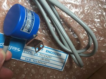
| Brand Name: | Tamagawa |
| Certification: | CE |
| Model Number: | TS5008N65 |
| Minimum Order Quantity: | 1pcs |
|---|---|
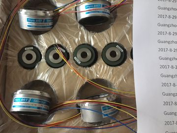
| Packaging Details: | carton |
| Delivery Time: | in stock |
| Payment Terms: | T/T, Western Union, MoneyGram |
| Supply Ability: | 100pcs/week |
| TAMAGAWA: | TAMAGAWA | TS5008N65: | TS5008N65 |
|---|---|---|---|
| Color: | Black | Material: | Iron |
| Temperature: | 20-90 | Japan: | Japan |
| Dimension: | 70mm | Wire: | Wire |
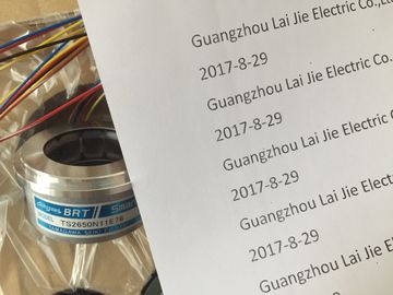
TS-5008-N-65
| Frequency measurement 0.04 Hz - 400 kHz | evaluation |
| Period duration measurement 2.5 μs - 25 s | Unit can be defined by userIncremental encoders for signals, 24 V, asymmetric, |
| Pulse encoders with/without direction |
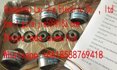
Guang Zhou Lai Jie Electric Co.,LTD
Please contact with “Tommy” for the price
TS3617N381
TS4514N2002E200
TS3617N1E1
TS1922N3
TS4603N2002E200
TS2097N1E9
TS2151N1E26
TS3617N3E9
TS4514N2405E200
TS3617N1E2
TS2014N181E32
TS4603N7002E200
TS4602N6321E100
TS3617N2E4
TS3617N13E9
TS4515N1202E200
TS3617N11E1
TS2014N182E32
TS1505N55
TS4515N6000E200
TS4603N1000E100
TS3617N2E5
TS3617N40E3
TS4515N2405E200
TS3617N1E3
TS2014N185E32
TS4602N1000E200
TS4603N1000E200
TS3617N2E6
TS5214N566
TS5205N450
TS5213N551
TS5208N122
TS5208N23
TS5778N171
TS5210N53
TS5320N510
TS5000N632
TS5212N510
TS5213N510
TS5312N616
TS208N101
TS5208N130
TS5213N530
TS5013N68
TS5214N566
TS5200N500
signal,
Pulse encoders up/down
Incremental encoders for signals to
RS-422 (5 V differential signal),
Pulse encoders with/without direction
signal,
Pulse encoders up/down,
Absolute encoders (SSI)
Max. count frequency 200 kHz:
800 kHz with pulse quadruplication
1 MHz
4 MHz with pulse quadruplication
Integrated DI 3 DIs per counter channel for
• Start
• Stopp
• Capture
• Synchronization
2 DIs per counter channel for
• Start
• Stopp
• Capture
• Synchronization
Integrated DQ 2 DQs for comparators and limit
values
2 DQs for comparators and limit
values
Counting functions Comparator
Adjustable counting range,
Incremental position detection
Comparator
Adjustable counting range,
Incremental
and absolute position detection
Measuring functions Frequency
Period duration
Velocity
Frequency
Period duration
VelocityExtremely high requirements on precision and speed can be met with time-based IO - regardless of
the performance of the controller and the fieldbus. Time-based IO ensures that signals are output
with a precisely defined response time. The I/O signals are processed on a time basis. The table
below shows the main features of the technology module for time-based IO.
The table below shows the main features of the technology module for time-based IO. 200 kHz with quadruple evaluation
Integrated DI Up to 8 DIs with the following functions:
• Up to 2 time stamps per cycle (resolution 1 µs)
• 32x oversampling
• Counting function up to 50 kHz
• Incremental encoder acquisition with 2 phase-shifted tracks
• Configurable input filter to suppress interference
Integrated DQ Up to 16 DQs with the following functions:
• Up to 2 time stamps per cycle (resolution 1 µs)
• 32x oversampling
• Pulse-width modulated output
• Configurable substitute values per DQThe power supply of an automation system to be
dimensioned according to plant size. A system
power supply is already integrated in the CPUs. Depending on the plant size,
you can expand the integrated system power supply with up to two additional system power supply
modules. If your plant has high power requirements, you can also connect load power supply
modules. In this case, the CPU/interface module and system power supply feed electricity into the
backplane bus. The supplied power is added together.
The main differences between the two power supplies for the automation system
are listed below: Supplies only internally required system voltage.
Supplies parts of the module electronics and the LEDs.
A system power supply can also supply CPUs or interface modules if these
are not connected to a 24 V DC load power supply.
Load power supply (PM) For input and output circuits of the plant's modules, sensors and actuators. In order to ensure the supply of the modules from the backplane bus, the infed power is compared
with the required power in the engineering system.
As early as in the planning stages, make sure that the power fed into the backplane bus is always
greater than or equivalent to the power drawn.System power supplies supply the internal electronics of the modules with power via the
backplane bus. The table below shows the available system power supply modules: System power supplies supply the internal electronics of the modules with power via the
backplane bus. The table below shows the available system power supply modules: The front connectors are used to wire the I/O modules. For modules with EMC critical signals, such
as analog modules and technology modules, the front connectors also need a shield contact.
The front connectors are available for 35 mm modules with screw terminals and push-in terminals
and for 25 mm modules with push-in terminals.
The shield contact consists of shield bracket and shield terminal. Together with the shield terminal,
the shield bracket allows the low-impedance connection of cable shields with minimum installation
times. The shielding takes place without tools and is included in the scope of delivery. The controllers are integrated into the Totally Integrated Automation Portal. Engineering
with the TIA Portal offers configuration and programming, common data storage and a uniform
operating concept for control, visualization and drives.
The TIA Portal simplifies the integrated engineering in all configuration phases of a plant. You can use the free Automation Tool to run commissioning and maintenance activities
simultaneously on various S7 stations as bulk operation independently of the TIA Portal.
The Automation Tool provides a multitude of functions: